The Proper Care and Feeding of NSImage
[This was the topic of my presentation at the NYC Cocoaheads meeting last night. I thought it would be nice to also post on the topic here.]
[I’ve received email from Ken Ferry. See addendum at the bottom]
NSImage is a troublesome class. Over the years, it’s been misunderstood and abused. I think much of this is because of a lack of conceptual clarity in the docs and examples and the API itself can be confusing and misleading. Add to this having to mix with CGImage and CIImage and you can end up with a confused mess.
The way I like to think of NSImage is that it’s a semantic image. When you look at icons, they are made up of several versions at different resolutions. Technically, it’s 4 or 5 images but NSImage wraps those all up into one notion of an image. Semantically, it is an icon of, say, a house but underneath it’s made up of several actual images of a house. The main reason for these different versions is that some graphics do not scale well and it helps to have hand tuned versions, especially for the smaller sizes. You can also do things like omit certain features in the smaller sizes to simplify the graphics and make the icon more recognizable.
One key misunderstanding is the notion that NSImage has actual image data. While there are parts of the API that deal with a cached bitmap (more on this below), NSImage itself is not based on image data. It is best to think of NSImage as a mediator between the image data in the various representations and the drawing context.

Loading an image from a file and drawing it is usually straightforward. If there are multiple representations, NSImage will figure out the correct one to use when drawing it. Most of this is automatic and is an important key to understanding how to use NSImage. As you will see further on, bypassing this mechanism leads to many issues with size and resolution mismatches when processing NSImages.
I’ve created a little program to help illustrate the points in this article. Since it also includes a new reusable class, I’ve included it in my NoodleKit repo. I suggest checking it out. Just compile and run the ImageLab target (you may need to set the active executable in XCode in the project menu). The rest of this article will be referring to it so I recommend you run it while reading the rest.
When you launch the app, it will load the test image. It’s just a colored circle. Now resize the window. You’ll see that the color changes as you resize. The icon itself is made up of four different sized images and to make it clear which representation is being used, I made the circle different colors for each one. Whenever the color changes when you resize, NSImage is switching to a different representation based on the size. Here’s what the different reps look like in Preview:

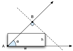
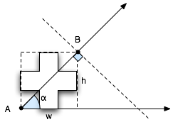
Size is another confusing aspect of NSImage. One thing to remember is that size is not pixels. It represents a coordinate space. One way to think of it is that NSImage’s size is like NSView’s frame while NSImageRep’s size is like NSView’s bounds. For NSImage, its size is a suggested size to draw the image in the user coordinate space. If possible, it’s best to explicitly specify the destination rect.
Let’s take the case of drawing some custom graphics on top of an existing icon with several representations, like drawing a badge over your app icon. A common way to do this is to lock focus on the NSImage, do your drawing, unlock focus and then draw the resulting image. What -lockFocus actually does is allow you to draw into a cache. This has probably lead to a lot of the misunderstanding that NSImage holds image data. Unfortunately, there are issues with this approach. Mainly, because there is no context about where this image will be drawn so the resulting image is tied to a specific resolution. Also, you are editing a cache so none of this image data is reflected in the original image reps and actually, from poking around, it’s actually destructive in that it may end up removing any other representations.
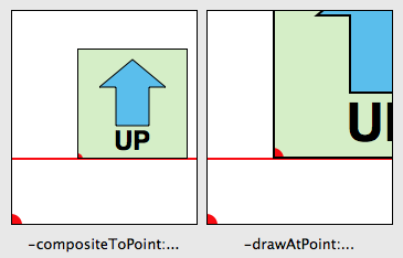
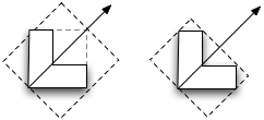
In our case here we are modifying an icon with different sized representations, what we end up doing is locking the resulting image into the size that happened to be set on the original NSImage. In many cases, you may not know how and where this icon will be used but if any scaling is involved, you may end up having an icon with the wrong version being displayed. In the example program, select “Modified (lock focus)” in the pop-up. Here it picks the 64×64 version (as indicated by the green circle) which becomes a problem when you scale the image up as shown on the left in the image below.

The one on the right is a version which uses an NSImageRep subclass (select “Modified (custom image rep)” in the pop-up). Notice that it picks the appropriate size as you resize the window. Why is this the case? It’s because NSImage doesn’t ask the image rep to draw until the NSImage itself is drawn. At that point, you actually have information about the destination, including how big it will actually appear on screen. NSImage is able to use this context to determine the right match between different sized images and the resolution of the output context. The same goes for any drawing code.
Subclassing NSImageRep is quite easy; you just need to override the -draw method. I’ve made it even easier by providing NoodleCustomImageRep which takes a block, allowing you to create images without creating a new subclass.
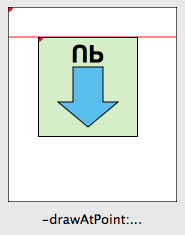
Say, though, you are drawing an image that should scale without pixellation, like drawing a square. Surely, you can just lock focus on an NSImage and draw a square and scale that as needed? Well, Mr Smarty Pants, take a look at the example program. Select “Drawn (lock focus)” in the pop-up.

Here, you’ll see odd fuzziness around the edges. What’s going on here? It’s not anti-aliasing but instead the graphics context where the image is being drawn has image interpolation turned on. As a result, the AppKit is trying to interpolate the image from it’s original size to a much bigger size.
How do you fix this? You could try turning off image interpolation in the destination graphics context but this isn’t always possible or desirable. The better solution is just like before: use a custom image rep to do the drawing (select “Drawn (custom image rep)” from the pop-up). Since the drawing occurs at drawing time, instead of image creation time, it knows about the context it is drawing into and therefore can provide your drawing code with a context at the correct resolution. The crisp square on the right speaks for itself.
Let’s take another example. Say we want to take an existing image and run a Core Image filter on it. Somehow you have to convert your NSImage into a CIImage. This usually entails a game of connecting up various methods that fit together until you got a CIImage. A common way to do this is:
ciImage = [CIImage imageWithData:[nsImage TIFFRepresentation]];
This dumps the whole image (all of its representations) into TIFF format which is in turn, re-parsed back into data. Now, CIImage is pixel based so it ends up picking one of the representations. It’s not documented which representation is picked since there’s no way to specify the context where it will be drawn so there’s a chance it won’t be the right one. Select “Core Image (TIFF Rep)” in the pop-up and you get something like the image on the left (or maybe you won’t; read on):

Now, it doesn’t look too bad here. It took the highest res representation and used that. That said, technically, it’s not correct. The version on the right (select “Core Image (custom rep)”) shows the correct image rep being used. Also, my experience has shown that the representation chosen by the -imageWithData: method can be different on different hardware and that it ignores the size set on the original NSImage so you may not be so lucky depending on what machine your code runs on.
Fortunately, Snow Leopard introduced a new method: -CGImageForProposedRect:context:hints:. As mentioned before, when you draw an NSImage into a context, it will automatically pick the right representation for that context. This method does basically the same thing but without the drawing part. Instead it returns a CGImage which you can then use to create your CIImage:
cgImage = [nsImage CGImageForProposedRect:&rect context:[NSGraphicsContext currentContext] hints:nil];
ciImage = [CIImage imageWithCGImage:cgImage];
Keep in mind, though, that it the image returned might not be the exact size you wanted. This becomes more of an issue when you are combining multiple images together in a CIImage pipeline and you need them all to be the same size. You can adjust for this by using CIImage’s -imageByApplyingTransform:.
In addition to the above method, Snow Leopard introduced -bestRepresentationForRect:context:hints: which does a similar thing but returns an image rep instead. Depending on your needs, you can use one or the other to tap NSImage’s image matching logic.
Finally, a note about performance. NSImage does keep a cache based on the drawing context. This helps for when you repeatedly draw the same image at the same size over and over. If you end up sharing an NSImage across different contexts, you’ll find that you are defeating the cache. For these cases, you should be copying the NSImages. Remember that NSImages are just mediators between image data and drawing context. NSImageReps are the actual image sources and, starting with 10.6, reps like NSBitmapImageRep do copy-on-write making it inexpensive to copy NSImages and their reps.
In the example app, there’s a field which shows the time taken to display the image. You’ll notice that when you resize the window, the cases which use a custom image rep are slower as it has to recache whereas the lockFocus cases don’t since the image is static. If this becomes an issue, you can turn off caching or use a fixed resolution image during a live resize. Another more subtle piece of business is performance when drawing from the cache. If you click the “Redisplay” button, it will cause the image to be displayed again. Since you aren’t changing the size, the cached version can be used. Notice how the versions using the custom image rep are usually a smidgen faster than the lockFocus versions. I suspect what is happening is when you lockFocus on the image, you lock the cache into a specific version and size. As a result, if you are drawing at any other size, it has to scale the cached image every time. With a custom image rep, it’s cached at the exact size so the cache can be used as is.
What are the lessons here?
- When defining your image, you should use an NSImageRep subclass and override -draw. If you don’t want to create a whole subclass just to create an image, use my NoodleCustomImageRep (included in NoodleKit) which allows you to pass in a drawing block. Using an image rep gives your drawing code better contextual information than you would get just drawing in a
-lockFocus. - If you follow point #1, then you can let NSImage make the decision of which representation to use. Use one of the drawing methods,
-CGImageForProposeRect:...or-bestRepresentationForRect:...and you’ll get the best sized representation for the job. Do not assume, though, that this representation will be the actual size you want. When drawing, it also helps to specify the rect to draw into. - Avoid using
-lockFocus. It doesn’t produce the correct image in different contexts and can be destructive in terms of kicking out the other reps in the NSImage. While still ok in specific circumstances, you have to know what you are doing. - If using the same NSImage in different contexts, copy it. In 10.6 onwards, this is an inexpensive operation as bitmap data is copy-on-write. Copying NSImages is is also a good idea in case some decides to use -lockFocus on the image (see #3).
If you have access to it, I highly recommend watching the video for Ken Ferry’s session at WWDC 2009: Session 111: NSImage in Snow Leopard (you may need a developer account to view/download it). Much of this is derived from that presentation and it has even more interesting bits about NSImage than what I’ve presented here.
And in case you missed it above, you can find NoodleKit (which contains NoodleCustomImageRep as well as the example program) here.
Addendum (Apr. 18, 2011):
I received an email from Ken Ferry himself pointing out a couple things. Mainly, that as of 10.6, lock focusing doesn’t draw into the cache anymore. It creates a representation whose context is suited for the main display. It is still good for images which are meant for that context. Also as the NSImage context will maintain any size-to-pixel ratio that is on the main display, it can still be used in this situation should resolution independence come into play. It’s not much different than before in this respect but it’s not as volatile as a cache, which I believe is the key point here.
That said, all the caveats above about using -lockFocus still hold true. It’s not so great for when the image needs to be scaled or if you have representations you want to keep (it does remove all other reps when you lock focus). Also, because the representation is tied to the machine, it’s not very suitable for persisting.
Comment » | Cocoa, Downloads, Icons, OS X, Programming, Quartz, User Interface